

Low Center
Electric Motors
Low Center Electric Motors Flat Asynchronous
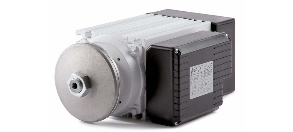
SOGA low center electric motors are high-quality Italian-made motors specifically designed for wood, marble, granite, and stone processing machines.
Available in series MR58-MR107 with power ranging from 0.75 to 21.6 kW, they come in single-phase and three-phase versions with various pole options (2, 4, 6). These motors feature compact dimensions, high protection ratings (IP55-IP65), reliability even in harsh operating conditions, and comply with European quality standards.
The extruded aluminum construction with C45 steel shaft and optional braking systems makes them an ideal choice for industrial equipment requiring compact, durable, and efficient solutions.
Browse by model size:

*r is the radial size of the motor.
2p- two poles | 4p- four poles | 6p- six poles
Or filter in shop by phase and poles:


Pₙ – power (kW), n – speed (rpm), η – efficiency (%), cos φ – power factor, Iₙ – current nominal (A), Iₛₚ/Iₙ – start current ratio, Mₙ – torque nominal (Nm), Mₛₚ/Mₙ – start torque ratio, m – weight (kg)

MR 58 Electric Motor Dimensions Table

Clockwise rotation standard (left thread). Anticlockwise rotation on request.


* only feet version.
MR 65 feet version dimensions:


MR 65 NO feet version dimensions:


Clockwise rotation standard (left thread). Anticlockwise rotation on request.


MR 71feet Electric Motor dimensions:


Clockwise rotation standard (left thread). Anticlockwise rotation on request.


MR80 Electric Motor dimensions:


Clockwise rotation standard (left thread). Anticlockwise rotation on request.


MR93 Electric Motor dimensions:

Clockwise rotation standard (left thread). Anticlockwise rotation on request.

MR 107
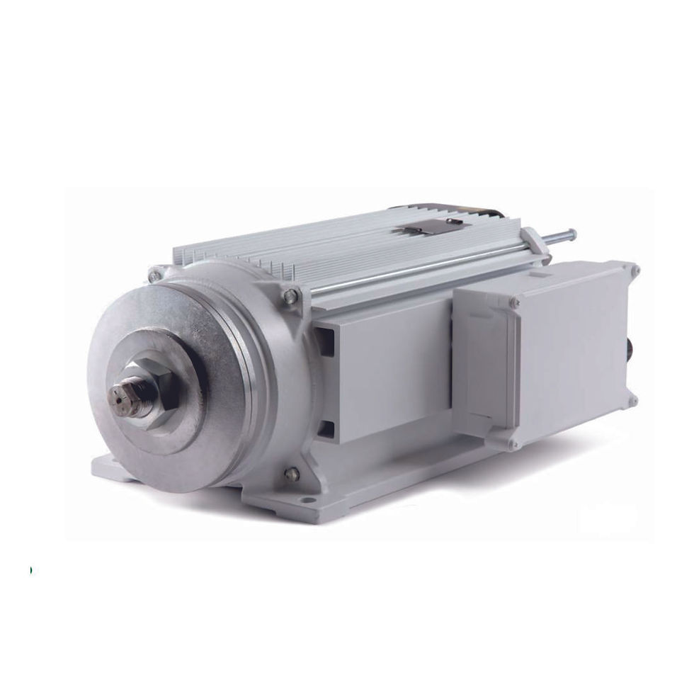
MR107 is a three-phase asynchronous low center motor for installation on bridge machines for cutting granite, marble or stone. The technical features and the choices of the adopted materials make this motor suitable for heavy duty applications and environments. As a matter of fact, the use of O-rings, V-rings, chromium-plated steel labyrinth and sealing gaskets between shields and housing, makes this motor IP65 totally protected against water and dust. It is available in three versions (2, 4, 6 poles). On request it can be supplied in two-speed-version or with electromagnetic brake with unchanged overall length.
The given output refers to S6-60% duty cycle.


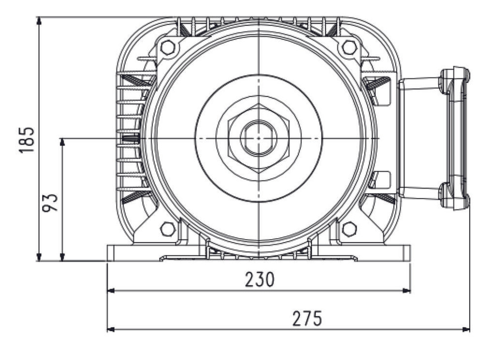
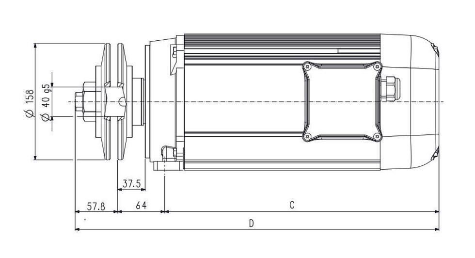
MR107 Electric Motor dimensions:
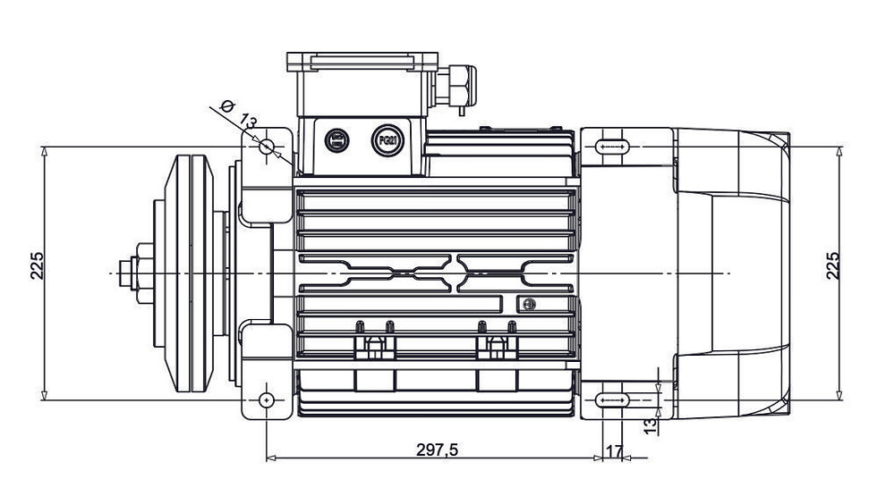


Clockwise rotation standard (left thread). Anticlockwise rotation on request.
1* O-ring, 2* Seal-ring, 3* Steel labyrinth ring


Technical information
WARNING
On motors having coupling flange with threaded holes, we recommend not to use too long fixing screws, in aim to avoid any risk of electrical dangers. In addition, the not-used holes of the flange must be sealed properly.
SPECIAL EXECUTIONS
On request it is possible realizing special executions: clock-wise or anti-clock-wise rotation, shaft upon drawing, shield and front flange drilling, switches equipped with cable and thermal protection, PTC thermal sensors or clixon thermal protectors, space heaters, B3 constructive shape etc.
GENERAL FEATURES
-
Standards: MR series motors are manufactured in compliance with IEC 60034-1 international standard. They also comply with the following European legislation rules: Directive 2014/35/EU, Directive 2014/30/EU, Directive 2011/65/EU
-
Protection degree: IP55 from MR58 to MR93 series; IP65 on MR107 series.
-
Constructive materials: Structural extruded aluminium housing, cage-type die-cast aluminium rotor, C45-steel shaft, self- lubricating double-shield radial ball-bearings dimensioned for heavy duty, nylon* fans, heat-resistant fan-covers. Aluminium** blade-holding flanges, equipped with tightening nut.
-
Terminal box: Three-phase MR motors: stiffened-polyamide* terminal box. Single-phase MR motors: heat-resistant* box suitable to give place to the capacitor, the terminal board or eventual connections to external switches.
*aluminium on request
**cast iron flanges on MR107 series
Main duty types for rotating electrical machines (IEC-EN 60034-1)
Duty type S1 – Continuous running duty • the motor is put in operation at a constant load for a sufficient T-time
to allow the machine reach the thermal equilibrium (see figure 1).
Duty type S3 – Intermittent periodic duty • the motor is put in operation following a sequence of Tc identical
duty cycles, each including a time of operation at constant load ∆tP and a ∆tR time at rest (the motor is turned off).
The cycle is too brief to reach the thermal equilibrium (see figure 2). The starting current does not significantly affect
the temperature rise.
The duration of the cycles is of 10 minutes (if not differently specified).
Example: S3 30% • during a 10-minute-cycle, the motor is put in operation at rated output for 3 minutes while it is
turned off for 7 minutes.
Duty type S6 – Continuous-operation periodic duty • the motor is put in operation following a sequence of Tc
identical duty cycles, each including a time of operation at constant load ∆tp and a time of operation at no-load ∆tV
(the motor is fed but at no load). The cycle is too brief to reach the thermal equilibrium (see figure 3). The duration of
the cycles is of 10 minutes (if not differently specified).
Example: S6 60% • during a 10-minute-cycle, the motor is put in operation at rated output for 6 minutes and it keeps
being fed but it idles for 4 minutes.


P = Load
Pᵥ = Electrical losses
θ = Temperature
θₘₐₓ = Maximum temperature attained
t = Time
T꜀ = Time of one load cycle
Δtₚ = Operation time at constant load
ΔtR = Time at rest and de-energized
Δtᵥ = Operation time at no load